Design for Manufacture
Creating the 3D model and designing the best cut procedure
Any component to be manufactured will typically be specified by the customer with a CAD model, detailed drawing and set of instructions including material specifications and any finishing treatment to be applied. The first job for Supercraft is to package the component specification into a route card which will travel with the component throughout its journey in the workshop.
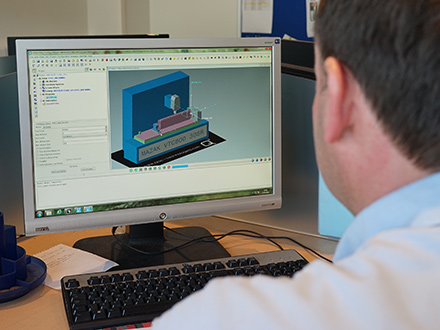
When the job arrives in the CAM programming department the component to be manufactured will either have 2D detailed drawings, in which case a 3D CAD model will be created to aid programming, or the customer will have designed the component in 3D CAD software and supplied the 3D model in a number of possible file formats or the preferred CATIA format. A CATIA 3D model provides one single reference for 100% of the product definition - all in 3D. This means that there is a single source of all product information, including a fully accurate and annotated geometric definition.
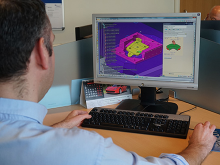
The next stage is to specify the machine cutting procedure. The 3D model is the starting point for a solid component to be produced from a single billet of raw metal. Within CATIA, a 3D model of the component is positioned within a 3D model of the billet of raw metal. Each part for manufacture needs to be matched to the capabilities and parameters of a machine in the workshop. The experienced CAM programmer specifies how the component is to be cut from the 3D stock billet, specifying the machine required to machine the component and aligning the component to the specified grain direction of the metal billet.
A proven aerospace manufacturing technique captures the majority of complex components in a two stage machining operation. During the first stage operation the standard fixing holes are machined into the billet to match a matrix of threaded and location holes, allowing the billet to be located and bolted securely to the machine plinth. The cutting procedures are programmed in the most efficient order to ensure design integrity and economy of production, starting with large diameter cutters and working down in diameter to produce finer finishing cuts. In the second stage operation all the excess material is removed until the component is just held in place by 0.25mm production tags. The component part can then be broken out of the surrounding production excess by hand and the break-out burr removed in a subsequent finishing procedure.